 |
 |
 |
| Главная Журналы Популярное Audi - почему их так назвали? Как появилась марка Bmw? Откуда появился Lexus? Достижения и устремления Mercedes-Benz Первые модели Chevrolet Электромобиль Nissan Leaf |
Главная » Журналы » Metal oxide semiconductor 1 ... 29 30 31 32 33 34 35 ... 91 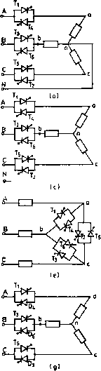 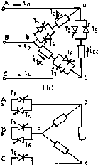 T2 td) 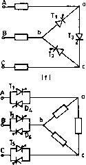 t>2 Ih) FIGURE 16.11 Three-phase ac voltage-controller circuit configurations. to be rated to carry hne currents and withstand phase voltages, whereas in Fig. 16.11b they should be capable of carrying phase currents and withstand the hne voltages. Also, in Fig. 16.11b the line currents are free from triplen harmonics while these are present in the closed delta. The power factor in Fig. 16.11b is slightly higher. The firing angle control range for both these circuits is 0 to 180° for i-load. The circuits in Fig. 16.11c and d are three-phase three-wire circuits and are difficult to analyze. In both these circuits, at least two SCRs - one in each phase - must be gated simultaneously to get the controller started by estabhshing a current path between the supply hnes. This necessitates two firing pulses spaced at 60° apart per cycle for firing each SCR. The operation modes are defined by the number of SCRs conducting in these modes. The firing control range is 0 to 150°. The triplen harmonics are absent in both these configurations. Another configuration is shown in Fig. 16.1 le when the controllers are delta connected and the load is connected between the supply and the converter. Fiere, current can flow between two hnes even if one SCR is conducting, so each SCR requires one firing pulse per cycle. The voltage and current ratings of SCRs are nearly the same as those of the circuit in Fig. 6.11b. It is also possible to reduce the number of devices to three SCRs in delta as shown in Fig. 16.1 If connecting one source terminal directly to one load circuit terminal. Each SCR is provided with gate pulses in each cycle spaced 120° apart. In both Figs. 16.1 le and f each end of each phase must be accessible. The number of devices in Fig. 16.1 If is fewer but their current ratings must be higher. As in the case of the single-phase phase-controUed voltage regulator, the total regulator cost can be reduced by replacing six SCRs by three SCRs and three diodes, resulting in three-phase half-wave controlled unidirectional ac regulators as shown in Fig. 16.1 Ig and h for star- and delta-connected loads. The main drawback of these circuits is the large harmonic content in the output voltage, particularly the second harmonic because of the asymmetry. Fiowever, the dc components are absent in the line. The maximum firing angle in the half-wave controUed regulator is 210°. 16.3.2 Fully Controlled Three-Phase Three-Wire AC Voltage Controller 16.3.2.1 Star-Connected Load with Isolated Neutral The analysis of operation of the fuU-wave controUer with isolated neutral as shown in Fig. 16.11c is, as mentioned, quite complicated in comparison to that of a single-phase controUer, particularly for an RL or motor load. As a simple example, the operation of this controUer is considered here with a simple star-connected i-load. The six SCRs are turned on in the sequence 1-2-3-4-5-6 at 60° intervals and the gate signals are sustained throughout the possible conduction angle. The output phase voltage waveforms for a = 30, 75, and 120° for a balanced three-phase i-load are shown in Fig. 16.12. At any interval, either three SCRs or two SCRs, or no SCRs may be on and the instantaneous output voltages to the load are either line-to-neutral voltages (three SCRs on), or one-half of the line-to-line voltage (two SCRs on) or zero (no SCR on). Depending on the firing angle a, there may be three operating modes. Mode I (also known as Mode 2/3): 0 < a < 60°. There are periods when three SCRs are conducting, one in each phase for either direction and periods when just two SCRs conduct. For example, with a = 30° in Fig. 16.12a, assume that at cot = 0, SCRs T5 and are conducting, and the current through the i-load in a-phase is zero making v = 0. At cot = 30°, Tl receives a gate pulse and starts conducting; T5 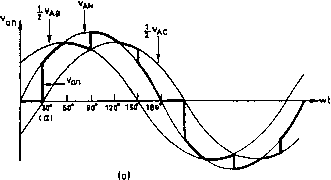 fVAB 1 fvAC 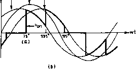  FIGURE 16.12 Output voltage waveforms for a three-phase ac voltage controller with star-connected i?-load: (a) yn a = 30°; (b) yn a = 75°; and (c) v = 120°. turned on, continues to conduct while T5 turns off as Vq is negative; v = l/2vj. When t2 is turned on at 135°, is turned off and v = 1/2vjq. The next SCR to turn on is T3, which turns off and 1; = 0. One SCR is always turned off when another is turned on in this range of a and the output is either one-half line-to-line voltage or zero. Mode III (also known as Mode 0/2): 90° < a< 150°. When none or two SCRs conduct. For a = 120° (Fig. 16.12c), earlier no SCRs were on and v = 0. At a = 120°, SCR is given a gate signal while has a gate signal already applied. As Vj is positive, and are forward-biased and they begin to conduct and v = 1/21;дв. Both Tl and turn off when 1;дв becomes negative. When a gate signal is given to t2, it turns on and turns on again. For a > 150°, there is no period when two SCRs are conducting and the output voltage is zero at a = 150°. Thus, the range of the firing angle control is 0 < a < 150°. For star-connected R-load, assuming the instantaneous phase voltages as ian = sin cot v = V2V,sin(cot- 120°) = V2V,sin(cot- 240°) (16.17) the expressions for the rms output phase voltage can be derived for the three modes as 0 < a < 60° V = V 60° < a < 90° = V, 90° < a < 150° = 3a 3 . 1---\--sin2a 271 An nl/2 - + - sin 2a + sin(2a + 60°) 2 An (16.18) nl/2 7- + -sin(2a + 60°) 4 2n An (16.19) nl/2 and remain on and v = 1;д^. The current in T5 reaches zero at 60°, turning T5 off. With and staying on, v = 1/2i;ab. At 90°, t2 is turned on, the three SCRs T, t2, and are then conducting and v = Vj-. At 120°, turns off, leaving and t2 on, so Vj- = 1/2vjq. Thus with the progress of firing in sequence until a = 60°, the number of SCRs conducting at a particular instant alternates between two and three. Mode II (also known as Mode 2/2): 60° < a < 90°. Two SCRs, one in each phase, always conduct. For a = 75° as shown in Fig. 16.12b, just prior to a = 75°, SCRs T5 and were conducting and v = 0. At 75°, is (16.20) For star-connected pure L-load the effective control starts at a > 90° and the expressions for two ranges of a are: 90° < a < 120° = 120° < a < 150° y, = Vs 5 3a 3 . ----\--sm 2a 2 я 2я 5 За 3 . , -- -+ -sin(2a + 60°) z п zn (16.21) (16.22) 0.8; to. 6 > о > 0.Д 0.2-
0 30 60 90 120 150 180 Firing Angle (a) FIGURE 16.13 Envelope of control characteristics for a three-phase full-wave ac voltage controller. The control characteristics for these two limiting cases (ф = 0 for i-load and ф = 90° for L-load) are shown in Fig. 16.13. Fiere, also, as in the single-phase case the dead zone may be avoided by controUing the voltage with respect to the control angle or hold-off angle (7) from the zero crossing of current in place of the firing angle a. RL Load. The analysis of the three-phase voltage controUer with star-connected RL load with isolated neutral is quite complicated as the SCRs do not cease to conduct at voltage zero and the extinction angle P is to be known by solving the transcendental equation for the case. The Mode-II operation, in this case, disappears [1] and the operation-shift from Mode I to Mode III depends on the so-called critical angle a [2, 4], which can be evaluated from a numerical solution of the relevant transcendental equations. Computer simulation either by PSPICE program [3, 7] or a switching-variable approach coupled with an iterative procedure [11] is a practical means of obtaining the output voltage waveform in this case. Figure 16.14 shows typical simulation results, using the later approach [11] for a three-phase voltage-controller-fed RL load for a = 60, 90, and 105°, which agree with the corresponding practical osciUograms given in reference [5]. Delta-Connected R-load, The configuration is shown in Fig. 16.11b. The voltage across an i-load is the corresponding line-to-line voltage when one SCR in that phase is on. Figure 16.15 shows the line and phase currents for a = 120° and 90° with an i-load. The firing angle a is measured from the zero crossing of the line-to-line voltage and the SCRs are turned on in the sequence as they are numbered. As in the single-phase case, the range of firing angle is 0 < a < 180°. The line currents can be obtained from the phase currents as = U - Ъ = bc ~ (16.23) The line currents depend on the firing angle and may be discontinuous as shown. Due to the delta connection, the triplen harmonic currents flow around the closed delta and do not appear in the hne. The rms value of the line current varies between the range 2/д < 4,rms < Iaj. (16.24) 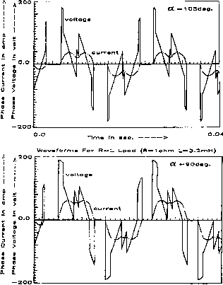 Time In с.----> 0.04. Wav ferme For R-U Load (R-lohm L-3.2nnH> 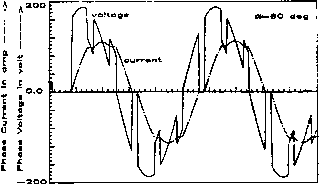 Tim. In о.----> - FIGURE 16.14 Typical simulation results for three-phase ac voltage-controller-fed RL load (R = 1 ohm, L = 3.2mH) for a = 60, 90, and 105°. lab О n \ \ зп tea 0 4i iob-4o 0 FIGURE 16.15 Waveforms of a three-phase ac voltage controller with a delta-connected i?-load: (a) a = 120°; (b) a = 90°. as the conduction angle varies from very smaU (large a) to 180° (a = 0). 16.4 Cycloconverters In contrast to the ac voltage controUers operating at constant frequency discussed so far, a cycloconverter operates as a direct ac/ac frequency changer with an inherent voltage control feature. The basic principle of this converter to construct an alternating voltage wave of lower frequency from successive segments of voltage waves of higher frequency ac supply by a switching arrangement was conceived and patented in the 1920s. Grid-controlled mercury-arc rectifiers were used in these converters installed in Germany in the 1930s to obtain 16-Hz single-phase supply for ac series traction motors from a three-phase 50-Hz system whUe at the same time a cycloconverter using 18 thyratrons supplying a 400-hp synchronous motor was in operation for some years as a power station auxiliary drive in the United States. However, the practical and commercial utihzation of these schemes waited untU the SCRs became available in the 1960s. With the development of large power SCRs and microprocessor-based control, the cycloconverter today is a matured practical converter for application in large-power low-speed variable-voltage variable-frequency (VWF) ac drives in cement and steel roUing miUs as weU as in variable-speed constant-frequency (VSCF) systems in aircraft and naval ships. A cycloconverter is a naturally commuted converter with the inherent capability of bidirectional power flow and there is no real limitation on its size unlike an SCR inverter with commutation elements. Here, the switching losses are considerably low, the regenerative operation at fuU power over complete speed range is inherent, and it delivers a nearly sinusoidal waveform resulting in minimum torque pulsation and harmonic heating effects. It is capable of operating even with the blowing out of an individual SCR fuse (unlike the inverter), and the requirements regarding turn-off time, current rise time and dvjdt sensitivity of SCRs are low. The main hmitations of a naturally commutated cycloconverter are: (i) hmited frequency range for subharmonic-free and efficient operation; and (ii) poor input displacement/power factor, particularly at low output voltages. 16.4.1 Single-Phase/Single-Phase Cycloconverter Though rarely used, the operation of a single-phase to single-phase cycloconverter is useful to demonstrate the basic principle involved. Figure 16.16a shows the power circuit of a single-phase bridge-type cycloconverter, which is the same arrangement as that of the dual converter described in Chapter 11, Section 11.4. The firing angles of the individual two-pulse two-quadrant bridge converters are continuously modulated here so that each ideally produces the same fundamental ac voltage at its output terminals as marked in the simplified equivalent circuit in Fig. 16.16b. Because of the unidirectional current-carrying property of the individual converters, it is inherent that the positive half-cycle of the current is carried by the P-converter and the negative half-cycle of the current by the iV-converter regardless of the phase of the current with respect to the voltage. This means that for a reactive load, each converter operates in both the rectifying and inverting region lb Vs 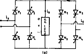 Vc 4. fi -50Hz 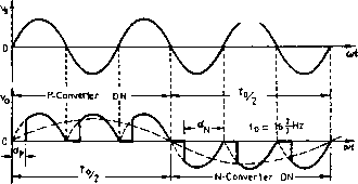 FIGURE 16.17 Input and output waveforms of a 50 to 16~Hz cycloconverter with RL load. 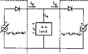 PO)nverter N-Converter Control circuit er=Ers n ot (Ы FIGURE 16.16 (a) Power circuit for a single-phase bridge cycloconverter; and (b) simplified equivalent circuit of a cycloconverter. 16Fiz cycloconverter. The P- and iV-converters operate for all alternate periods. The output frequency (1/T) can be varied by varying and the voltage magnitude by varying the firing angle a of the SCRs. As shown in the figure, three cycles of the ac input wave are combined to produce one cycle of the output frequency to reduce the supply frequency to one-third across the load. If (Xp is the firing angle of the P-converter, the firing angle of the iV-converter as is я - dp and the average voltage of the P-converter is equal and opposite to that of the iV-converter. The inspection of the waveform with a remaining fixed in each half-cycle generates a square wave having a large low-order harmonic content. A near approximation to sine wave can be synthesized by a phase modulation of the firing angles as shown in Fig. 16.18 for a 50 to 10-Fiz cycloconverter. The harmonics in the load-voltage waveform are fewer compared to the earlier waveform. The supply current, however, contains a subharmonic at the output frequency for this case as shown. during the period of the associated half-cycle of the low-frequency output current. Operation with R-Load, Figure 16.17 shows the input and output voltage waveforms with a pure P-load for a 50 to Operation with RL Load, The cycloconverter is capable of supplying loads of any power factor. Figure 16.19 shows the idealized output voltage and current waveforms for a lagging power factor load where both the converters are operating as rectifier and inverter at the intervals marked. The load current 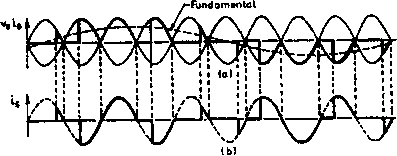 P-Convtrter N-Converter. 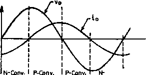 ifTverting neclifylng inverHng Conv. I rectifying FIGURE 16.19 with RL load. Load voltage and current waveform for a cycloconverter lags the output voltage and the load-current direction determines which converter is conducting. Each converter continues to conduct after its output voltage changes polarity, and during this period the converter acts as an inverter and the power is returned to the ac source. The inverter operation continues until the other converter starts to conduct. By controlhng the frequency of osciUation and the depth of modulation of the firing angles of the converters (as wiU be shown later), it is possible to control the frequency and the amplitude of the output voltage. The load current with RL load may be continuous or discontinuous depending on the load phase angle ф. At hght load inductance or for ф < a < я, there may be discontinuous load current with short zero-voltage periods. The current wave may contain even harmonics as weU as subharmonic components. Further, as in the case of a dual converter, though the mean output voltage of the two converters are equal and opposite, the instantaneous values may be unequal and a circulating current can flow within the converters. This circulating current can be limited by having a center-tapped reactor connected between the converters or can be completely eliminated by logical control simUar to the dual converter case when the gate pulses to the converter remaining idle are suppressed when the other converter is active. In practice, in addition, a zero current interval of short duration is needed between the operation of the P- and iV-converters to ensure that the supply lines of the two converters are not short-circuited. With circulating current-free operation, the control SPHOHzSUPPUr f43R0llP I* ! CfTh PA Rconverter 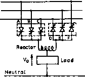 iilllirnil ThnAT Fundamental output vol 1  №CROUP -OK- -OK- -OK- -0 --0 - -? <J- Variable voltage -8 Variable frequenc) с Out put to 3-phase Fundamental output current 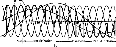 - Inversioi FIGURE 16.20 (a) Three-phase half-wave (three-pulse)cycloconverter supplying a single-phase load; (b) three-pulse cycloconverter supplying a three-phase load; (c) output voltage waveform for one phase of a three-pulse cycloconverter operating at 15 Hz from a 50-Hz supply and 0.6 power factor lagging load. scheme becomes complicated if the load current is discontinuous. For the circulating current scheme, the converters are kept in virtually continuous conduction over the whole range and the control circuit is simple. To obtain a reasonably good sinusoidal voltage waveform using the hne-commutated two-quadrant converters, and to ehminate the possibility of the short circuit of the supply voltages, the output frequency of the cycloconverter is hmited to a much lower value of the supply frequency. The output voltage waveform and the output frequency range can be improved further by using converters of higher pulse numbers. 16.4.2 Three-Phase Cycloconverters 16.4.2.1 Three-Phase Three-Pulse Cycloconverter Figure 16.20a shows a schematic diagram of a three-phase half-wave (three-pulse) cycloconverter feeding a single-phase load, and Fig. 16.20b shows the configuration of a three-phase half-wave (three-pulse) cycloconverter feeding a three-phase load. The basic process of a three-phase cycloconversion is illustrated in Fig. 16.20c at 15 Fiz, 0.6 power factor lagging load from a 50-Fiz supply. As the firing angle a is cycled from zero at a to 180° at j, half a cycle of output frequency is produced (the gating circuit is to be suitably designed to introduce this osciUation of the firing angle). For this load it can be seen that although the mean output voltage reverses at X, the mean output current (assumed sinusoidal) remains positive until Y. During ХУ, the SCRs A, B, and С in the P-converter are inverting. A similar period exists at the end of the negative half-cycle of the output voltage when D, £, and F SCRs in the iV-converter are inverting. Thus the operation of the converter follows in the order of rectification and inversion in a cyclic manner, with the relative durations being dependent on the load power factor. The output frequency is that of the firing angle oscillation about a quiescent point of 90° (condition when the mean output voltage, given by = Vjcosa, is zero). For obtaining the positive half-cycle of the voltage, firing angle a is varied from 90 to 0° and then to 90°, and for the negative half-cycle, from 90 to 180° and back to 90°. Variation of a within the limits of 180° automatically provides for natural line commutation of the SCRs. It is shown that a complete cycle of low-frequency output voltage is fabricated from the segments of the three-phase input voltage by using the phase-controlled converters. The P or iV-converter SCRs receive firing pulses that are timed such that each converter delivers the same mean output voltage. This is achieved, as in the case of the single-phase cycloconverter or the dual converter, by maintaining the firing angle constraints of the two groups as ap = (180° - a). Fiowever, the instantaneous voltages of two converters are not identical and a large circulating current may result unless limited by an intergroup reactor as shown (circulating-current cycloconverter) or completely suppressed by removing the gate pulses from the nonconducting converter by an intergroup blanking logic {circulating-current-free cycloconverter). Circulating-Current Mode Operation. Figure 16.21 shows typical waveforms of a three-pulse cycloconverter operating with circulating current. Each converter conducts continuously with rectifying and inverting modes as shown and the load is supplied with an average voltage of two converters reducing some of the ripple in the process, with the intergroup reactor behaving as a potential divider. The reactor hmits the circulating current, with the value of its inductance to the flow of load current being one fourth of its value to the flow of circulating current as the inductance is proportional to the square of the number of turns. The fundamental wave produced by both the converters are the same. The reactor voltage is the instantaneous difference between the converter voltages, and the time integral of this voltage divided by the inductance (assuming negligible circuit resistance) is the circulating current. For a three-pulse cycloconverter, it can be observed that this current reaches its peak when dp = 60° and = 120°. Output Voltage Equation. A simple expression for the fundamental rms output voltage of the cycloconverter and the required variation of the firing angle a can be derived with the assumptions that: (i) the firing angle a in successive half-cycles is varied slowly resulting in a low-frequency output; (ii) the source impedance and the commutation overlap are neglected; (iii) the SCRs are ideal switches; and (iv) the Rectifying  Inverting Inverting 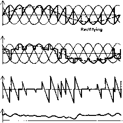 P-Converter Output voltoge N-Converter Output velloge Output voltoge at lood Reactor voltage Circulating current current is continuous and ripple-free. The average dc output voltage of a p-pulse dual converter with fixed a is Vdo = Vdomaxcosa, whcrc У^, = J-vn- (16.25) % p For the p-pulse dual converter operating as a cycloconverter, the average phase voltage output at any point of the low frequency should vary according to the equation (16.26) where Vimax is the desired maximum value of the fundamental output of the cycloconverter. Comparing Eq. (16.25) with Eq. (16.26), the required variation of a to obtain a sinusoidal output is given by a = cos [(y,i/Vdomax)sina;,t] = cos [r sinco.t] (16.27) where r is the ratio (Vai,max/domax) the voltage magnitude control ratio. Equation (16.27) shows a as a nonlinear function with r(< 1) as shown in Fig. 16.22. However, the firing angle ap of the P-converter cannot be reduced to 0° as this corresponds to = 180° for the N-converter, which, in practice, cannot be achieved because of aUowance for commutation overlap and finite turn-off time of the SCRs. Thus the firing angle dp can be reduced to a certain finite value а^ the maximum output voltage is reduced by a factor cos а^- 180 150 120 о 90 и 60 30 0
0 60 120 180 2/.0 300 360 wt (deg) - FIGURE 16.22 Variations of the firing angle (a) with r in a cycloconverter. The fundamental rms voltage per phase of either converter is Vnr = у ON = oP = rVnb -sin- (16.28) Although the rms value of the low-frequency output voltage of the P-converter and that of the iV-converter are equal, the actual waveforms differ and the output voltage at the midpoint of the circulating current limiting reactor (Fig. 16.21), which is the same as the load voltage, is obtained as the mean of the instantaneous output voltages of the two converters. Volte 9€ Current Desired output P-conv. voltage N-conv. voltage voUageL 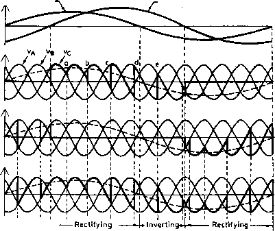 U Inverting 4* FIGURE 16.23 Waveforms for a three-pulse circulating current-free cycloconverter with RL load. Circulating-Current-Free Mode Operation, Figure 16.23 shows the typical waveforms for a three-pulse cycloconverter operating in this mode with RL load assuming continuous current operation. Depending on the load current direction, only one converter operates at a time and the load voltage is the same as the output voltage of the conducting converter. As explained earlier in the case of the single-phase cycloconverter, there is a possibility of a short-circuit of the supply voltages at the crossover points of the converter unless care is taken in the control circuit. The waveforms drawn also neglect the effect of overlap due to the ac supply inductance. A reduction in the output voltage is possible by retarding the firing angle gradually at the points a, b, c, d, e in Fig. 16.23 (this can easily be implemented by reducing the magnitude of the reference voltage in the control circuit). The circulating current is completely suppressed by blocking aU the SCRs in the converter that is not delivering the load current. A current sensor is incorporated in each output phase of the cycloconverter that detects the direction of the output current and feeds an appropriate signal to the control circuit to inhibit or blank the gating pulses to the nonconducting converter in the same way as in the case of a dual converter for dc drives. The circulating current-free operation improves the efficiency and the displacement factor of the cycloconverter and also increases the maximum usable output frequency. The load voltage transfers smoothly from one converter to the other. Three-Phase Six-Pulse and Twelve-Pulse Cycloconverter, A six-pulse cycloconverter circuit configuration is shown in Fig. 16.24. Typical load-voltage waveforms for 6-pulse (with 36 SCRs) and 12-pulse (with 72 SCRs) cycloconverters are shown in Fig. 16.25. The 12-pulse converter is obtained by connecting two 6-pulse configurations in series and appropriate transformer connections for the required phase-shift. It may be seen that the higher pulse numbers wiU generate waveforms closer to the desired sinusoidal form and thus permit higher frequency output. The phase loads may be isolated from each other as shown or interconnected with suitable secondary winding connections. 16.4.3 Cycloconverter Control Scheme Various possible control schemes (analog as weU as digital) for deriving trigger signals for controUing the basic cycloconverter have been developed over the years. Out of the several possible signal combinations, it has been shown [12] that a sinusoidal reference signal (e = sin cot) at desired output frequency and a cosine modulating signal (e = E cos CO it) at input frequencyis the best combination possible for comparison to derive the trigger signals for the SCRs (Fig. 16.26 [15]), which produces the output waveform with the lowest total harmonic distortion. The modulating voltages can be obtained as the phase-shifted voltages (B-phase for A-phase SCRs, C-phase voltage for B-phase SCRs, and so on) as explained in Fig. 16.27, where at the intersection point a E sm(cDit - 120°) = sm(cDj - ф) cos(cOit - 30°) = (E/EJ sm(cot - ф) From Fig. 16.27, the firing delay for A-phase SCR a = (cot- 30°). Thus, cos a = (E/EJ sm((D,t - ф). The cycloconverter output voltage for continuous current operation V, = Vdo cos a = VMEJ sm(co,t - ф) (16.29) which shows that the amplitude, frequency and phase of the output voltage can be controlled by controlling correspondence parameters of the reference voltage, thus making the transfer characteristic of the cycloconverter linear. The derivation of the two complimentary voltage waveforms for the P-group or iV-group converter blanks in this way is iUustrated in Fig. 16.28. The final cycloconverter output waveshape is composed of alternate half-cycle segments of the complementary P-converter and iV-converter output voltage waveforms that coincide with the positive and negative current half-cycles, respectively. Control Circuit Block Diagram, Figure 16.29 [16] shows a simphfied block diagram of the control circuit for a circulating 3*Phase input в mvlmnn- 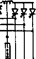 -Voltage Current Desired output Load voltage Load voUagc  FIGURE 16.25 Cycloconverter load-voltage waveforms with lagging power factor load: (a) 6-pulse connection; and (b) 12-pulse connection. Co Cc modulating v/ove 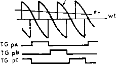 FIGURE 16.26 Deriving firing signals for one converter group of a 3-pulse cycloconverter. 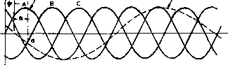 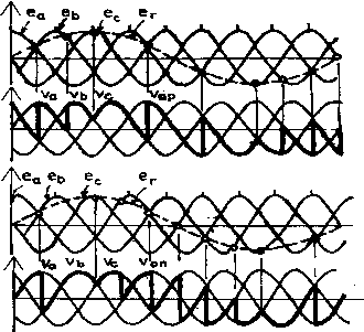 FIGURE 16.27 Derivation of the cosine modulating voltages. FIGURE 16.28 Derivation of P-converter and Л^-converter output voltages. 1 ... 29 30 31 32 33 34 35 ... 91 |
|
© 2026 AutoElektrix.ru
Частичное копирование материалов разрешено при условии активной ссылки |